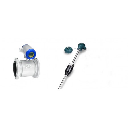
Magnetic Energy Flowmeter

The RBEF-H In-line electromagnetic energy flowmeter ideal for conductive liquids.It used to measure individual energy consumption in any liquid heating/cooling systems  A wide variety of sizes are available to accommodate nominal pipe diameters ranging from ½" through 120". The RBEF-H may be used in many applications that require accurate thermal energy measurement such as chilled water, hot water and condenser water systems.


Description

  • Principle
  • Features
  • Specification
  • Model Selection
  • Applicants
  • Download
Principle
Features

Electromagnetic Energy Flowmeter Features:


  • Flow velocity range: 0.1-15m/s
  • Variety of lines: 1/4"-120"(DN6 - 3000mm)
  • Designed for clear water ≥5uS/cm
  • IP68 Enclosure that can be used for underground application
  • High accuracy of 0.2%, 0.25%, 0.5%
  • Empty pipe, current excitation and battery capacity;
  • Real time display of supply / return water temperature, instantaneous flow rate, cooling consumption value, heating consumption value, instantaneous power, total flow rate etc.
  • Four different units of measurements available: MJ, GJ, kWh/h, MWh/h.
  • Pt1000 3-wire Temperature Sensor
  • NIST traceable calibration certificate
  • CE Certificated......
Specification

Electromagnetic Energy Flowmeter Specification:

Sizes

Flanged (Metric)

DN6…DN3000

Flanged (US)

1/4”…118”

Wafer Design

DN15…DN100

Nominal Pressure

GB,JIS and DIN Flange

0.6 MPa, 1.0 MPa, 1.6 MPa, 4.0 MPa

ANSI Flange

Class 150, Class 300

Wafer Design

1.6 MPa, 4.0 MPa

For additional pressure requirements, please contact manufacturer

Accuracy (pulse output)

Standard

±0.5%   (0.6m/sec to 12 m/sec)

Optional

±0.2%   (1.0m/sec to 12 m/sec)

Measurement Resolution

±1mm/sec

Max Flow Tube Velocity

SI:

49 ft/s

US:

12 m/s

Ambient Temperature

-25…+55°C   /   -13…+131°F

Relative Humidity

5%…90%

Conductivity

≥5 μS/cm

Transmitter Mounting Availability

Compact type

Sizes:     DN15…DN1000

       1/2”…40”

Remote type

Sizes:     DN15…DN3000

       1/2”…118”

Note 1: Cable between flow tube and remote transmitter is type SMFE100

Note 2: Remote unit supplied with 10m cable as standard

Note 3: Max cable length is 200m (650ft)


Material

SI

US

Liner Material Options

Neoprene (std)

DN15…DN3000

1/2”…118”

PTFE

DN15…DN1000

1/2”…40”

Polyurethane

DN15…DN300

1/2”…12”

PFA

DN15…DN250

1/2”…10”

PFA with optional wire reinforcement

DN80…DN250

3”…10”

Tefzel

DN15…DN250

1/2”…10”

Tefzel with optional wire reinforcement

DN80…DN250

3”…10”


ceramic liner and electrodes

DN15…DN200

1/2”…8”

Electrode Material Options

316L stainless steel (std)

DN15…DN3000

1/2”…118”

Hastelloy – C22

DN15…DN1000

1/2”…40”

Hastelloy – B10

DN15…DN1000

1/2”…40”

Titanium

DN15…DN250

1/2”…10”

Tantalum

DN15…DN250

1/2”…10”

Platinum/iridium Alloy

DN15…DN250

1/2”…10”

316L with tungsten carbide coating

DN15…DN600

1/2”…24”

Grounding Options

Flange Grounding

DN15…DN3000

1/2”…56”

Grounding Ring

DN15…DN250

1/2”…10”

Electrode Grounding

DN50…DN3000

2”…118”

Inlet protection ring

DN50…DN300

2”…12”


Type

Liner

Standard

Optional

Max Process Temperature Limits

Compact

Neoprene

80°C / 176°F

120°C / 248°F

PTFE

80°C / 176°F

120°C / 248°F

Polyurethane

80°C / 176°F

-

PFA

80°C / 176°F

120°C / 248°F

Tefzel

80°C / 176°F

-

Remote

Neoprene

80°C / 176°F

120°C / 248°F

PTFE

80°C / 176°F

120°C / 248°F

180°C / 356°F

Polyurethane

80°C / 176°F

-

PFA

80°C / 176°F

120°C / 248°F

Tefzel

80°C / 176°F

-

Environmental Protection Class

Compact

IP 65

IP67

Remote

IP 65

IP 68

Power Supply Options

85…265VAC / 45…63Hz, 20VA

16…36VDC, 16VA

Display

2 or 3 line backlit LCD

Configuration Access

Front panel keypad

Hand held infrared remote control (optional)

Output Signals

Active analog current output

Max load resistance      0…1.5kΩ for 0…10mA

                     0…750Ω for 4…20mA

Accuracy = same as pulse output ±0.1% of rate

Option: HART Protocol

Passive analog current output

Requires 24Vdc external supply to operate

Accuracy = same as pulse output ±0.1% of rate

Pulse / frequency and alarm outputs

Optically isolated open collector output powered either internally or externally

  Int. power:        28VDC with 1.2kΩ pull-up resistor

  Ext. power:       ≤36VDC, max current 250mA

Digital Communications

RS485 Modbus

GPRS (superimposed on current output)

All interfaces have built in lightning protection

Electrical isolation

Isolation between all I/O and input power no less than 500V

Isolation between all I/O and ground no less than 500V

Isolation between flow tube and transmitter outputs no less than 500V

Temperature Sensor

Pt1000

Standard

JB/T 9248-1999 Electromagnetic Flowmeter

Model Selection

Model RBEF-H Electromagnetic Energy Flowmeter(BTU Meter) Ordering Code

RBEF-H 

DN

-


-


-


-


-


-


-


-


-


-


-


-


-


1


2


3


4


5


6


7


8


9


10


11


12


13


14

15

16


1 Nominal Diameter(mm)/ [inches] (1)

0015 [½”]

0100 [4”]

0450 [18”]

1400 [56”]

0020 [¾”]

0125 [5”]

0500 [20”]

1600

0025 [1”]

0150 [6”]

0600 [24”]

1800

0032 [1¼]

0200 [8”]

0700 [28”]

2000

0040 [1½]

0250 [10”]

0800 [32”]

2200

0050 [2”]

0300 [12”]

0900 [36”]

2400

0065 [2½]

0350 [14”]

1000 [40”]

2600

0080 [3”]

0400 [16”]

1200 [48”]

3000


2 Flange Rating (1)

02

0.25 MPa

1600 … 3000

06

0.6 MPa 

700 … 3000

10

1.0 MPa 

200 … 1400

16

1.6 MPa 

15 … 600

20

ANSI Class 150

15 …1400

40

4.0 MPa 

15 … 150

50

ANSI Class 300

15 … 1400

AA

Special


3 Electrode Material

1

316L Stainless Steel

3

Hastelloy C-22

4

Hastelloy B-10

5

Titanium

6

Tantalum

7

Platinum / Iridium Alloy

8

Tungsten Coated Stainless Steel

9

ceramic


4 Lining Material

1

Neoprene (Hard rubber)

≤ 3000

2

PTFE

≤ 1000

3

Polyurethane

≤ 300

4

PFA

≤ 250

5

Tefzel

≤ 250

6

PFA with Wire Net

80 … 250

7

Tefzel with Wire Net

80 … 250 

8

Ceramic

15 … 200

9

HDPE

≤ 1000


5 Grounding and Lining Protection

0

Flange ground

15 … 3000

1

Earth ring

15 … 250

 2

Ground electrode

50 … 3000

3

Inlet protection ring

50 … 3000


6 Max. Process Temperature

A

80°C

All Linings

B

120°C

Neoprene / PTFE / PFA / Tefzel

C

180°C

PTFE only


7 Environmental Protection Class

1

IP65

2

IP67 (Compact Type Only)

3

IP68 (Remote Type Only)


8 Explosion Proofing

1

None

2

Ex DE IIC T6


9 Configuration – sensor/transmitter 

1

Compact (15 … 1000)

2-X

Remote (with Xm cable, standard: 10m)(2)


10 Power Supply

A

AC: 85 … 265 VAC / 45 … 63Hz

D

DC: 18 … 36 VDC


11 Display and Programming

2

2 line LCD display + keypad programming

3

3 line LCD display + keypad programming


12 Output and Input

0

Basic Configuration (current, pulse and contact outputs)

1

Basic Configuration + RS485(MODBUS)

2

Basic Configuration + GPRS

3

Relay

4

Hart

5

PROFIBUS-DP


13 Calibration Specification

1

3 point, 0.5% accuracy

2

3 point, 0.25% accuracy

3

Special


14 Flow Tube Configuration


Flange Type

15 … 3000

D

DIN


A

ANSI


J

JIS


2

Wafer


3

Tri-clamp

1.5 -200

O

Others(pls clarify)


4

Flange type with removable electrodes

15 … 3000


15 Body + Flange material


C

Carbon Steel


S

304 Stainless Steel


16 Special Function

0

No

R

IR Remote

T

Power off timer

H

Cumulative hours

Q

Quantitative control

J

Relay Output

S

Input Switch


17 with Heat measuring

0

No

T

With Measuring heat function, with Pt-1000


Remark:  

(1) Line size selection will be inches for ANSI Class 150/300 rating selection, DIN size for all other ratings

(2) Order longer cable length separately

(3) Ceramic liner and electrodes is with wafer  and flange type only


Applicants

The RBEF-H Electromagnetic Energy Flowmeter Applicants:

  • HVAC/BTU Meter;
  • Heat/Cooling System;
  • Efficiency measuring and monitoring from central control rooms.
  • Energy consumption data source for energy management system, DCS, district-wide systems.
  • Energy-Customer Billing from accurately totalized Energy / MASS measurements.
  • chilled water, hot water, domestic water, condenser water and boiler feeds.
  • Basis for internal cost distribution using campus-wide systems.
  • Direct Energy / MASS measurements at both Boiler and “point of use” locations.
Download

product search