


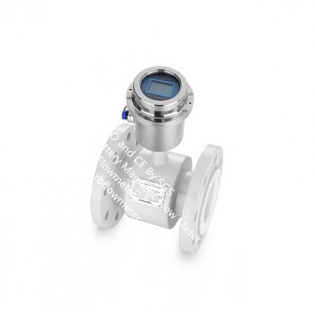


RBXEF-B Electromagnetic water flow meters are based on electromagnetic flow (EMF) technology and provide measurement of a wide flow range.Special for Irrigation Magmeters.
RBEFB Series battery-powered electromagnetic flowmeter converter is specifically designed for water resources and industries. It is widely used in the cases without power supply, such as: city water supply, sewage treatment, water conservancy, water administration and water resources industries. It can reach accuracy of 1.0, 0.5 or 0.2 when working with ordinary electromagnetic flowmeter sensors. The RBEFB Series battery-powered electromagnetic flow converter is generally equipped with a set of four lithium batteries typically lasting 3 - 6 years. Longer running life can be obtained if more battery set is used.
Micro-power 16-bit embedded processor was implemented to generate the sensor excitation circuit and manage the lithium battery power efficiently. It features full digital signal processing, measurement stability, high measurement accuracy and anti-interference capability. The converter supplies automatic bi-directional flow measurement, self-diagnosis and system fault alarm. The measurement data can be transmitted through the powerful GSM / GPRS remote management software system to achieve the flow data storage, analysis and other functions remotely.
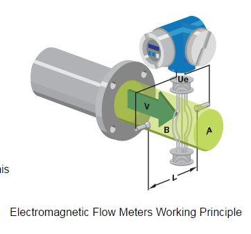
Faraday’s law of electromagnetic induction states that an inductive voltage is generated when a conductor moves through a magnetic field. This principle is used as the basis of flow measurement in the RBEF electromagnetic flow meter. In the electromagnetic flow meter, the flowing fluid corresponds to the moving conductor as described in Faraday’s law.
UE ∞ B * D * v
The induced voltage UE is directly proportional to magnetic field intensity (B), electrode spacing (D) and average fluid velocity (v). Since magnetic field intensity (B) and the electrode spacing (D) are constant values, induced voltage UE is therefore directly proportional to the average flow velocity (v).
Q = (∏ * D2) / 4 * v therefore UE ∞ Q
The equation for calculating volumetric flow rate (Q) shows that the induced voltage (UE) is linear and directly proportional to the average velocity (v). In the flowmeter transmitter, the induced voltage (UE) from the electrodes is used to calculate volumetric flow rate (Q) based upon the pipe’s internal diameter.
UE = Induced voltage
B = Magnetic field strength
D = Electrode spacing
V = Fluid velocity
Q = Instantaneous volumetric flow rate
RBXEF-B Battery-powered Magnetic Water Meter designed for water and wastewater industry to accurately measure the water flow in closed conduits.
RBEFB Battery Electromagnetic Water Meter is special ideal for remote locations in municipal, irrigation, wastewater treatment and industrial liquid processes industries where no power connection is available and IP68 for underwater projects.
RBXEF-B Battery Magnetic Water Meter Specification
Data Table:
|
|
R200 |
R500 |
||||||
|
Pipe size |
Q1 |
Q2 |
Q3 |
Q4 |
Q1 |
Q2 |
Q3 |
Q4 |
|
DN50 |
0.315 |
0.504 |
63.00 |
78.75 |
0.126 |
0.202 |
63.00 |
78.75 |
|
DN65 |
0.500 |
0.800 |
100.00 |
125.00 |
0.200 |
0.320 |
100.00 |
125.00 |
|
DN80 |
0.800 |
1.280 |
160.00 |
200.000 |
0.320 |
0.512 |
160.00 |
200.00 |
|
DN100 |
0.800 |
1.280 |
160.00 |
200.000 |
0.320 |
0.512 |
160.00 |
200.00 |
|
DN125 |
0.800 |
1.280 |
160.00 |
200.000 |
0.320 |
0.512 |
160.00 |
200.00 |
|
DN150 |
0.800 |
1.280 |
160.00 |
200.000 |
0.320 |
0.512 |
160.00 |
200.00 |
|
DN200 |
5.000 |
8.000 |
1000.00 |
1250.000 |
2.000 |
3.200 |
1000.00 |
1250.00 |
|
DN250 |
8.000 |
12.800 |
1600.00 |
2000.000 |
3.200 |
5.120 |
1600.00 |
2000.00 |
|
DN300 |
12.50 |
20.000 |
2500.00 |
3125.000 |
5.000 |
8.000 |
2500.00 |
3125.00 |
|
DN400 |
12.50 |
20.000 |
2500.00 |
3125.000 |
|
|
|
|
|
DN450 |
12.50 |
20.000 |
2500.00 |
3125.000 |
|
|
|
|
|
DN500 |
12.50 |
20.000 |
2500.00 |
3125.000 |
|
|
|
|
RBXEF-B Battery Magnetic Water Meter Model Selection
|
RBEFB-W- |
DN |
- |
|
- |
|
- |
|
- |
|
- |
|
- |
|
- |
|
- |
|
- |
|
- |
|
- |
|
- |
|
- |
|
|
|
|
1 |
|
2 |
|
3 |
|
4 |
|
5 |
|
6 |
|
7 |
|
8 |
|
9 |
|
10 |
|
11 |
|
12 |
|
13 |
|
14 |
15 |
|
1 Nominal Diameter(mm)/ [inches] (1)
|
|||||||||||||||||||||||||||||
|
2 Flange Rating (1)
|
|||||||||||||||||||||||||||||
|
3 Electrode Material
|
|||||||||||||||||||||||||||||
|
4 Lining Material
|
|||||||||||||||||||||||||||||
|
5 Grounding and Lining Protection
|
|||||||||||||||||||||||||||||
|
6 Max. Process Temperature
|
|||||||||||||||||||||||||||||
|
7 Environmental Protection Class
|
|||||||||||||||||||||||||||||
|
8 Explosion Proofing
|
|||||||||||||||||||||||||||||
|
9 Configuration – sensor/transmitter
|
|||||||||||||||||||||||||||||
|
10 Power Supply
|
|||||||||||||||||||||||||||||
|
11 Display and Programming
|
|||||||||||||||||||||||||||||
|
12 Output and Input
|
|||||||||||||||||||||||||||||
|
|
|||||||||||||||||||||||||||||
|
13 Calibration Specification
14 Flow Turndown
|
|||||||||||||||||||||||||||||
|
15 Flow Tube Configuration
|
RBXEF-B Battery Electromagnetic Water Meter Applications:
Catalog - Battery Magnetic Water Meter
Manual - Battery Electromagnetic Water Meter
Other files - Battery Emag Water Meter
Electromagnetic Flow Meter
Ultrasonic Flow Meter
Coriolis, Thermal Mass Flow Meter,Density Meter
Vortex, Turbure Flow Meter for liquid, gas and Steam
Other Process Instrument