


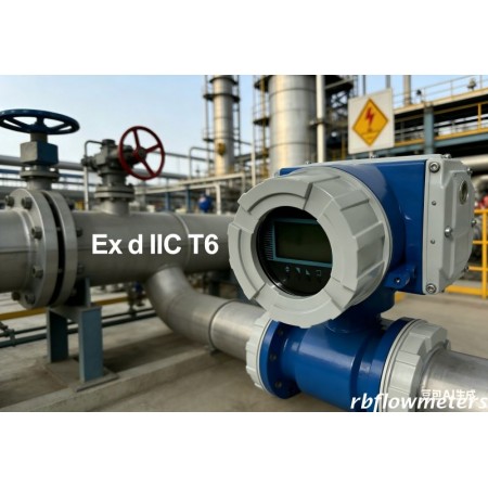

# Electromagnetic Flowmeter with Converter ## Selection Table for Petrochemical Industry ### 1. Selection by Medium Type | Medium | Recommended Lining | Recommended Electrode | Suitable Converter | Notes | |--------|--------------------|-----------------------|--------------------|-------| | Crude oil / Oil-water mixture | Polyurethane / Neoprene | 316L / Hastelloy C | High-precision (explosion-proof) | Applicable for oil & water with sufficient conductivity | | Sand-containing wastewater / Oilfield injection water | Wear-resistant polyurethane | Titanium / Hastelloy C | Industrial enhanced type | Wear-resistant, anti-scour | | Dilute acids & alkalis (HCl, NaOH) | PFA / F46 (PTFE) | Tantalum / Hastelloy C | Anti-corrosion type | Best for strong corrosive media | | Slurry / Coal-water slurry / Residual slurry | Wear-resistant polyurethane | 316L / Titanium | Anti-interference type | No clogging, no pressure loss | | Circulating water / Boiler water | Rubber | 316L | General type | Cost-effective & reliable | --- ### 2. Selection by Operating Conditions #### Temperature - Normal temperature (0–80°C): Rubber lining - Medium temperature (80–150°C): F46 / PFA - High temperature (150–180°C): PFA + high-temperature converter #### Pressure - Normal / Low pressure: PN16 - Medium pressure: PN25 / PN40 - High-pressure oilfield injection: PN63 / PN100 + high-pressure sensor #### Explosion Protection - Petrochemical & oil-gas zones: **Ex d IIC T6** explosion-proof converter required - Indoor safe area: Standard or intrinsic safety type --- ### 3. Standard Converter Functions - Output: 4–20mA + Pulse + RS485 (Modbus) - Display: Instant flow, total flow, percentage, fault codes - Features: Empty pipe detection, small signal cutoff, adjustable damping, self-diagnosis - Power supply: 24VDC / 220VAC (24VDC preferred in petrochemical plants) --- ### 4. Non-Applicable Media - Non-conductive media: gasoline, diesel, pure alcohol, etc. - Ultra-pure water with conductivity < 5μS/cm - High-temperature gas and steam --- ### 5. Quick Selection Guide - Electromagnetic flowmeters are ideal for crude oil and wastewater. - Choose wear-resistant or corrosion-resistant materials based on medium. - Use tantalum electrodes for acids & alkalis, PTFE for high temperatures. - Explosion-proof models are mandatory in oil and gas zones.
RBEFB battery powered electromagnetic flow water meter is designed specifically for the water industry to meet the city's water supply to ensure the accurate calculation, the scene is widely used in places without power supply, such as urban water supply, sewage treatment, water conservancy and other industries.
Battery-powered electromagnetic flow meter specially designed sensor excitation system, and high-performance lithium battery-powered systems, and uses 16-bit AMD embedded processor power, with all-digital signal processing, measurement stability, high measurement accuracy, anti - Interference ability, and other features, automatic bi-directional flow measurement, on-site instantaneous flow of positive and negative cumulative total to show that self-diagnosis alarm FAULT Far GSM wireless data functions, the user through the powerful GSM / GPRS remote management software system can flow Far total wireless data storage functions.
The magnetic flow meter fulfils the special customer demands to water applications within abstraction, distribution network, revenue metering as well as irrigation.
Precision irrigation for higher yields. The RB Irrigation Magmeter is specifically built for agricultural environments. Its full-bore design ensures zero pressure loss and prevents clogging from sand or debris. With an IP68 waterproof rating and optional battery power, it provides reliable flow data for farm water management and smart irrigation systems.
Faraday’s law of electromagnetic induction states that an inductive voltage is generated when a conductor moves through a magnetic field. This principle is used as the basis of flow measurement in the RBEF electromagnetic flow meter. In the electromagnetic flow meter, the flowing fluid corresponds to the moving conductor as described in Faraday’s law.
UE ∞ B * D * v
The induced voltage UE is directly proportional to magnetic field intensity (B), electrode spacing (D) and average fluid velocity (v). Since magnetic field intensity (B) and the electrode spacing (D) are constant values, induced voltage UE is therefore directly proportional to the average flow velocity (v).
Q = (∏ * D2) / 4 * v therefore UE ∞ Q
The equation for calculating volumetric flow rate (Q) shows that the induced voltage (UE) is linear and directly proportional to the average velocity (v). In the flowmeter transmitter, the induced voltage (UE) from the electrodes is used to calculate volumetric flow rate (Q) based upon the pipe’s internal diameter.
UE = Induced voltage
B = Magnetic field strength
D = Electrode spacing
V = Fluid velocity
Q = Instantaneous volumetric flow rate
RBEFB Battery powered Emag Flow Meter Features:
RBEFB Battery operated Emag Flow Meter Technical parameters
|
Diameter |
DN10-DN1200 DN150- DN1200 (Also optional plug-in battery-powered electromagnetic flow meter) |
|
Pressure |
0.6~4.0Mpa(Special pressure customizable) |
|
Accuracy |
±0.5%、±1.0% |
|
Measuring range |
0 ~±12m / s |
|
Media Measurement (conductivity) |
> 20μs/cm |
|
medium temperature |
-10 ℃ ~ 90 ℃, ≤180℃(Remote type) |
|
ambient temperature |
-40 ℃ ~ 65 ℃ |
|
power supply |
3.6V/DC built-in lithium battery-powered, continuous working hours, more than 6 years |
|
Electrode materials |
316L stainless steel, HC, HB, titanium, tantalum, platinum / iridium alloy |
|
lining materials |
poly chloroprene rubber, polyurethane rubber, PTFE, F46, PFA |
|
Connections |
flange type, plug-in, clip pattern |
|
Structure in the form of |
a body divided body |
|
Level of protection |
IP68 and IP65(Remote type) |
|
Display |
LCD large-screen liquid crystal display instantaneous flow of positive / reverse the cumulative total and prompt warning |
|
Output |
Local display(optional pressure display): 1. GPRS, RS485 can be powered by battery 2. 4-20mA, Pulse and 4-20mA+Hart is powered by 12-30VDC |
|
Means of communication |
GPRS(compact and remote type), GSM, Mobus, Hart |
Appearance and size of the installationTable
|
Diameter |
Pressure |
Dimension(mm) |
Weights |
Remark |
||||
|
(mm) |
MPa |
a |
b |
C |
d |
kgs |
|
|
|
25 |
4.0 |
200 |
146 |
121 |
115 |
5.5 |
||
|
32 |
200 |
161 |
139 |
140 |
6.5 |
|||
|
40 |
200 |
161 |
139 |
150 |
6.5 |
|||
|
50 |
200 |
199 |
160 |
165 |
7.5 |
|||
|
65 |
200 |
209 |
173 |
185 |
12 |
|||
|
80 |
200 |
216 |
173 |
200 |
12 |
|||
|
100 |
1.6 |
250 |
267 |
233 |
220 |
14 |
||
|
125 |
250 |
278 |
233 |
250 |
19 |
|||
|
150 |
300 |
308 |
257 |
285 |
22 |
|||
|
200 |
1.0/1.6 |
350 |
366 |
291 |
340 |
45 |
||
|
250 |
400 |
418 |
331 |
395 |
65 |
|||
|
300 |
500 |
481 |
381 |
445 |
95 |
|||
|
350 |
500 |
529 |
428 |
505 |
135 |
|||
|
400 |
600 |
587 |
483 |
565 |
170 |
|||
|
450 |
600 |
620 |
533 |
615 |
210 |
|||
|
500 |
600 |
675 |
585 |
670 |
230 |
|||
|
600 |
600 |
790 |
685 |
780 |
255 |
|||
|
700 |
700 |
900 |
800 |
895 |
315 |
|||
|
800 |
800 |
1015 |
905 |
1015 |
335 |
|||
|
900 |
900 |
1115 |
1002 |
1115 |
435 |
|||
|
1000 |
1000 |
1230 |
1110 |
1230 |
595 |
|||
|
1200 |
1200 |
1420 |
1295 |
1405 |
720 |
|||
Battery Working Time
Table 4.1.Corresponding Table of Battery life and Interval Measurement Time
(Excitation Mode 1)
|
Cycle Measuring Time |
50mA Excitation Use Time |
20mA Excitation Use Time |
|
30S |
120 months |
200 months |
|
15S |
60 months |
100 months |
|
14S |
56 months |
93 months |
|
13S |
52 months |
86 months |
|
12S |
48 months |
79 months |
|
11S |
44 months |
73 months |
|
10S |
40 months |
66 months |
|
9S |
36 months |
59 months |
|
8S |
32 months |
53 months |
|
7S |
28 months |
46 months |
|
6S |
24 months |
39 months |
|
5S |
20 months |
33 months |
|
4S |
16 months |
26 months |
|
3S |
12 months |
19 months |
Table 2 Battery Life Coefficient Corresponding Excitation Mode
|
Excitation Mode |
Mode 1 |
Mode 2 |
Mode 3 |
Mode 4 |
|
Battery Life Coefficient |
1.0 |
0.85 |
0.75 |
0.60 |
When the sensor has large diameter, the corresponding excitation cycle is long (see excitation mode parameter), therefore there is more power consumption.
RBEFB Battery operated Emag Flow Meter Model selection
|
RBEFB- |
DN |
- |
|
- |
|
- |
|
- |
|
- |
|
- |
|
- |
|
- |
|
- |
|
- |
|
- |
|
- |
|
- |
|
|
|
1 |
|
2 |
|
3 |
|
4 |
|
5 |
|
6 |
|
7 |
|
8 |
|
9 |
|
10 |
|
11 |
|
12 |
|
13 |
|
14 |
|
1 Nominal Diameter(mm)/ [inches] (1)
|
|||||||||||||||||||||||||||||
|
2 Flange Rating (1)
|
|||||||||||||||||||||||||||||
|
3 Electrode Material
|
|||||||||||||||||||||||||||||
|
4 Lining Material
|
|||||||||||||||||||||||||||||
|
5 Grounding and Lining Protection
|
|||||||||||||||||||||||||||||
|
6 Max. Process Temperature
|
|||||||||||||||||||||||||||||
|
7 Environmental Protection Class
|
|||||||||||||||||||||||||||||
|
8 Explosion Proofing
|
|||||||||||||||||||||||||||||
|
9 Configuration – sensor/transmitter
|
|||||||||||||||||||||||||||||
|
10 Power Supply
|
|||||||||||||||||||||||||||||
|
11 Display and Programming
|
|||||||||||||||||||||||||||||
|
12 Output and Input
|
|||||||||||||||||||||||||||||
|
13 Calibration Specification
|
|||||||||||||||||||||||||||||
|
14 Flow Tube Configuration
|
(1) Line size selection will be inches for ANSI Class 150/300 rating selection, DIN size for all other ratings
(2) Order longer cable length separately
(3) Ceramic liner and electrodes is with wafer type only
Battery operated Magmeter(Emag flow meter) Application
Catalog- Battery Powered Magnetic flow meter
Manual- Battery Powered Magnetic flow meter
Other Files - Battery Powered Magnetic flow meter
Electromagnetic Flow Meter
Ultrasonic Flow Meter
Coriolis, Thermal Mass Flow Meter,Density Meter
Vortex, Turbure Flow Meter for liquid, gas and Steam
Other Process Instrument