Open Channel MagMeters
DN100-6000
Width: max.6m
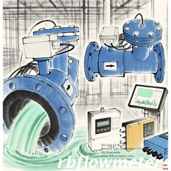
RBXEF-OP Open Channel Electromagnetic Flow Meter


A Complete Technical Guide for Engineers & Plant Managers
Based on RBEF‑P Series – Dedicated Partially Filled Pipe Electromagnetic Flow Meter
Technical Application Guide – 2025 Edition
1. Do You Really Need a “Partially Filled” Flow Meter?
In many industrial applications — wastewater treatment, stormwater drainage, irrigation, industrial discharge — pipelines often run partially full. Conventional electromagnetic flow meters require full pipe conditions to provide stable, accurate readings. When the pipe is not full, they may fail completely or produce erratic data.
It combines two independent measurements in one instrument:
The actual flow rate is then calculated as:
Q = Av × Vh
Where: Av = actual cross‑sectional area of the fluid (from h), and Vh = average flow velocity.
When evaluating a model, always verify these critical parameters (based on RBEF‑P series):
| Parameter | Typical Range / Requirement | Selection Tip |
|---|---|---|
| Pipe diameter (DN) | DN100 – DN1200 (4″–48″) | Smaller diameters ( |
| Liquid level range | 10% – 100% of pipe cross‑section | Below 10% accuracy may decrease |
| Flow accuracy (partially full) | ±2.5% FS | Full pipe mode can reach ±0.5% |
| Fluid conductivity | ≥50 μS/cm (standard) | Low conductivity → use special signal cables |
| Ambient temperature | -10°C to +55°C | High temperature media require special liners |
| Straight pipe run | Upstream ≥10D, Downstream ≥5D | Critical for stable velocity profile |
| Level input signal | 4–20 mA (two‑wire) | Meter provides 24V power for level sensor |
| Outputs | 4‑20mA, pulse, RS485 (MODBUS), alarms | Match with your control system |
| Grounding resistance | ≤10Ω | Essential to avoid EMI |
Poor installation is the #1 cause of measurement errors. Follow these five rules:
| Application | Recommended DN | Key Concern |
|---|---|---|
| Wastewater inlet | DN300–DN1000 | Fast level changes, debris |
| Stormwater drainage | DN400–DN1200 | Low conductivity, risk of submersion |
| Agricultural irrigation | DN150–DN500 | Battery option often preferred |
| Industrial discharge | DN100–DN600 | Corrosive media → ceramic liner |
| ❌ Mistake | ✅ Correct approach |
|---|---|
| Using any magmeter in partially filled pipes | Choose a dedicated partially filled pipe flow meter |
| Ignoring the 10% minimum level requirement | Keep level >10% of diameter |
| Placing the ultrasonic level sensor arbitrarily | Aim perpendicular to liquid surface; avoid blind zone (3 cm) |
| Skipping grounding | Always ground to ≤10Ω |
| Setting parameters once and forgetting | Re‑calibrate zero, damping, and empty‑pipe alarm on site |
Every application is different. For custom pipe sizes, special liners, or open‑channel requirements, contact our technical team.
RB Flowmeter
Website: www.rbflowmeters.com
Email: info@rbflowmeters.com rbflowmeters@gmail.com
Open Channel MagMeters
DN100-6000
Width: max.6m
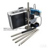
Portable Doppler
Open Channel
Partially Filled
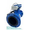
Partially Filled Pipes
DN100 - DN1400
Accuracy up to 2.5%