RBEF-E Mini Magmeter
2L/h Micro Flow|DN3-DN50
PEEK Liner for Chemical Dosing
RBEF-E Low Flow Inductive Magmeters


Introduction
In electromagnetic flow measurement, the induced signal is often as weak as a few millivolts. Without proper grounding, stray currents and electromagnetic interference can overwhelm this signal, leading to zero-point drift and unstable readings. Based on the RBEF Series 2026 User Manual, this guide outlines the mandatory grounding protocols for various industrial environments.
Why Grounding is Non-Negotiable
Proper grounding serves two critical functions:
1. Zero Potential Reference: It ensures the fluid and the sensor share the same electrical potential, creating a stable baseline for the electrodes.
2. Electromagnetic Shielding: It directs external noise and parasitic currents safely to the earth, preventing them from contaminating the measurement signal.
Grounding Procedures for Different Pipeline Types
1. Conductive Metal Pipelines (Unlined)
2. Non-Conductive or Lined Pipelines (PVC, PE, PTFE)
3. Pipelines with Cathodic Protection
Standard Grounding Checklist (RBEF Series 2026)
• Grounding Resistance: Always verify that the resistance is below 10Ω.
• Independence: Avoid "daisy-chaining" grounding wires with high-power equipment like VFDs (Variable Frequency Drives) or large motors.
• Signal Cable Integrity: For remote/split-type installations, ensure the shielded signal cable is grounded only at the converter end to prevent ground loops.
• Terminal Quality: Use O-type cold-pressed terminals for secure, vibration-resistant connections.
Correct grounding is the foundation of high-precision measurement. By following these RBEF-specific protocols, you can eliminate signal fluctuations and ensure your system operates at its peak performance of ±0.2% to ±0.5% accuracy.
Need technical assistance for your specific site? [Contact our Engineering Team for a Custom Grounding Plan]
RBEF-E Mini Magmeter
2L/h Micro Flow|DN3-DN50
PEEK Liner for Chemical Dosing
Ceramic Liner +Electrode
DN15 to DN300
Abrasive Slurries
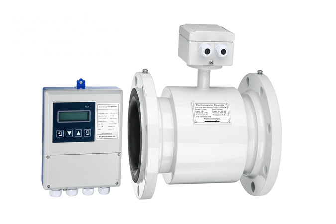
Type: Compact,Remote type
Multifunction
Custom languages
Pipe Size: DN15…DN3000
High Accuracy: ±0.2%
Flange, Wafer or Thread