


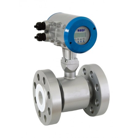

High Pressure Magmeters (Electromagnetic Flowmeter) is designed to measure the flow rates of conductive liquids in applications with high operating pressures.
It can be used in applications with pressures in excess of 6000 psig (42 Mpa), Line sizes ranging from 1" to 8" (25 mm to 200 mm) can be accommodated by the high pressured mag meter, with available process connections including ANSI, DIN, and JIS-type flanges.
A wide selection of options are also available for the display/converter module including Compact or remote type, 85-265 VAC or 16-36 VDC power, and HART, RS485 and Profibus communications.
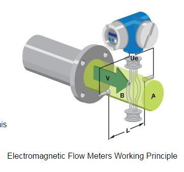
Faraday’s law of electromagnetic induction states that an inductive voltage is generated when a conductor moves through a magnetic field. This principle is used as the basis of flow measurement in the RBEF electromagnetic flow meter. In the electromagnetic flow meter, the flowing fluid corresponds to the moving conductor as described in Faraday’s law.
UE ∞ B * D * v
The induced voltage UE is directly proportional to magnetic field intensity (B), electrode spacing (D) and average fluid velocity (v). Since magnetic field intensity (B) and the electrode spacing (D) are constant values, induced voltage UE is therefore directly proportional to the average flow velocity (v).
Q = (∏ * D2) / 4 * v therefore UE ∞ Q
The equation for calculating volumetric flow rate (Q) shows that the induced voltage (UE) is linear and directly proportional to the average velocity (v). In the flowmeter transmitter, the induced voltage (UE) from the electrodes is used to calculate volumetric flow rate (Q) based upon the pipe’s internal diameter.
UE = Induced voltage
B = Magnetic field strength
D = Electrode spacing
V = Fluid velocity
Q = Instantaneous volumetric flow rate
High Pressure Magmeter (Emag.flow meter) Features:
High Pressure Magnetic Flow Meter(Magmeters) Specification:
|
Specification |
Data |
Specification |
Data |
|
Flow range |
0-12m/s |
Medium |
Conducting medium(Solid content ≤5%) |
|
Measuring repeatability |
± 0.1% |
Electrical Conductivity |
>5us/cm(water >20us/cm) |
|
Accuracy |
±0.5% |
Power |
220VAC/50Hz |
|
Pressure |
26MPa |
24VDC |
|
|
32MPa(special order) |
Output |
4-20mA |
|
|
Operation temp. |
0 to +80℃ |
Pulse |
0-1kHz(Adjustable) |
|
0 to + 45℃ |
Consumption |
10VA |
Dimensions
|
Pipe Size |
Working Pressure(MPa) |
a |
b |
c |
d |
Screw Size |
|
50 |
26 |
325 |
234 |
165 |
215 |
M24*8 |
|
65 |
26 |
330 |
256 |
190 |
246 |
M27*8 |
|
80 |
26 |
430 |
276 |
203 |
265 |
M30*8 |
|
100 |
26 |
440 |
308 |
241 |
310 |
M33*8 |
|
125 |
26 |
505 |
356 |
292 |
375 |
M39*8 |
Remark: 1. a is meter'length; b is Flange outside diameters; c is flange inside diameters; d is length of Magnetic Converter base to botton of pipe.
High Pressure Magnetic Flow Meter Model Selection
|
1 Nominal Diameter(mm)/ [inches] (1)
|
|||||||||||||||||||||||
|
2 Flange Rating (1)
|
|||||||||||||||||||||||
|
3 Electrode Material
|
|||||||||||||||||||||||
|
4 Lining Material
|
|||||||||||||||||||||||
|
5 Grounding and Lining Protection
|
|||||||||||||||||||||||
|
6 Max. Process Temperature
|
|||||||||||||||||||||||
|
7 Environmental Protection Class
|
|||||||||||||||||||||||
|
8 Explosion Proofing
|
|||||||||||||||||||||||
|
9 Configuration – sensor/transmitter
|
|||||||||||||||||||||||
|
10 Power Supply
|
|||||||||||||||||||||||
|
11 Display and Programming
|
|||||||||||||||||||||||
|
12 Output and Input
|
|||||||||||||||||||||||
|
|
|||||||||||||||||||||||
|
13 Calibration Specification
|
|||||||||||||||||||||||
|
14 Flow Tube Configuration
|
High Pressure Electromagnetic Flowmeter Typical applications:
Magmeters
Ultrassonic Flow Meter
Coriolis Mass Flow Meter
Other Flow Instrument