


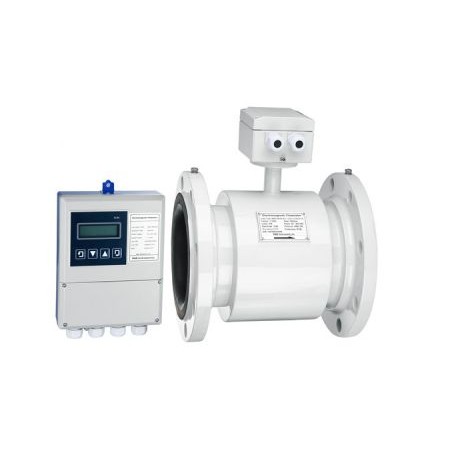


RBEF Electromagnetic Flow meter(Magmeter) is suitable to measure volumetric flow rate of the conductive liquid and slurry in the closed pipe. e.g. clean water, sewage, various solutions of acid, alkali, salt; slurry, slag, pulp and other liquids such as food-beverage etc.
A various type Magnetic Flow meters(Liquid flow meter) can provide as follows:
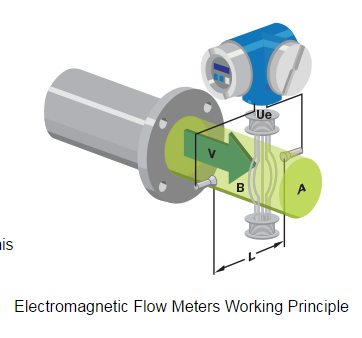
Faraday’s law of electromagnetic induction states that an inductive voltage is generated when a conductor moves through a magnetic field. This principle is used as the basis of flow measurement in the RBEF electromagnetic flow meter. In the electromagnetic flow meter, the flowing fluid corresponds to the moving conductor as described in Faraday’s law.
UE ∞ B * D * v
The induced voltage UE is directly proportional to magnetic field intensity (B), electrode spacing (D) and average fluid velocity (v). Since magnetic field intensity (B) and the electrode spacing (D) are constant values, induced voltage UE is therefore directly proportional to the average flow velocity (v).
Q = (∏ * D2) / 4 * v therefore UE ∞ Q
The equation for calculating volumetric flow rate (Q) shows that the induced voltage (UE) is linear and directly proportional to the average velocity (v). In the flowmeter transmitter, the induced voltage (UE) from the electrodes is used to calculate volumetric flow rate (Q) based upon the pipe’s internal diameter.
UE = Induced voltage
B = Magnetic field strength
D = Electrode spacing
V = Fluid velocity
Q = Instantaneous volumetric flow rate
|
Sizes |
Flanged (Metric) |
DN15…DN3000 |
||||||
|
Flanged (US) |
1/2”…118” |
|||||||
|
Wafer Design |
DN15…DN100 |
|||||||
|
Nominal Pressure |
GB,JIS and DIN Flange |
0.6 MPa, 1.0 MPa, 1.6 MPa, 4.0 MPa |
||||||
|
ANSI Flange |
Class 150, Class 300 |
|||||||
|
Wafer Design |
1.6 MPa, 4.0 MPa |
|||||||
|
For additional pressure requirements, please contact manufacturer |
||||||||
|
Accuracy (pulse output) |
Standard |
±0.5% (0.6m/sec to 12 m/sec) |
||||||
|
Optional |
±0.2% (1.0m/sec to 12 m/sec) |
|||||||
|
Measurement Resolution |
±1mm/sec |
|||||||
|
Max Flow Tube Velocity |
SI: |
49 ft/s |
||||||
|
US: |
12 m/s |
|||||||
|
Ambient Temperature |
-25…+55°C / -13…+131°F |
|||||||
|
Relative Humidity |
5%…90% |
|||||||
|
Conductivity |
≥5 μS/cm |
|||||||
|
Transmitter Mounting Availability |
Compact type |
Sizes: DN15…DN1000 1/2”…40” |
||||||
|
Remote type |
Sizes: DN15…DN3000 1/2”…118” |
|||||||
|
Note 1: Cable between flow tube and remote transmitter is type SMFE100 Note 2: Remote unit supplied with 10m cable as standard Note 3: Max cable length is 200m (650ft) |
||||||||
|
|
Material |
SI |
US |
|||||
|
Liner Material Options |
Neoprene (std) |
DN15…DN3000 |
1/2”…118” |
|||||
|
PTFE |
DN15…DN1000 |
1/2”…40” |
||||||
|
Polyurethane |
DN15…DN300 |
1/2”…12” |
||||||
|
PFA |
DN15…DN250 |
1/2”…10” |
||||||
|
PFA with optional wire reinforcement |
DN80…DN250 |
3”…10” |
||||||
|
Tefzel |
DN15…DN250 |
1/2”…10” |
||||||
|
Tefzel with optional wire reinforcement |
DN80…DN250 |
3”…10” |
||||||
|
|
ceramic liner and electrodes |
DN15…DN200 |
1/2”…8” |
|||||
|
Electrode Material Options |
316L stainless steel (std) |
DN15…DN3000 |
1/2”…118” |
|||||
|
Hastelloy – C22 |
DN15…DN1000 |
1/2”…40” |
||||||
|
Hastelloy – B10 |
DN15…DN1000 |
1/2”…40” |
||||||
|
Titanium |
DN15…DN250 |
1/2”…10” |
||||||
|
Tantalum |
DN15…DN250 |
1/2”…10” |
||||||
|
Platinum/iridium Alloy |
DN15…DN250 |
1/2”…10” |
||||||
|
316L with tungsten carbide coating |
DN15…DN600 |
1/2”…24” |
||||||
|
Grounding Options |
Flange Grounding |
DN15…DN3000 |
1/2”…56” |
|||||
|
Grounding Ring |
DN15…DN250 |
1/2”…10” |
||||||
|
Electrode Grounding |
DN50…DN3000 |
2”…118” |
||||||
|
Inlet protection ring |
DN50…DN300 |
2”…12” |
||||||
|
|
Type |
Liner |
Standard |
Optional |
||||
|
Max Process Temperature Limits |
Compact |
Neoprene |
80°C / 176°F |
120°C / 248°F |
||||
|
PTFE |
80°C / 176°F |
120°C / 248°F |
||||||
|
Polyurethane |
80°C / 176°F |
- |
||||||
|
PFA |
80°C / 176°F |
120°C / 248°F |
||||||
|
Tefzel |
80°C / 176°F |
- |
||||||
|
Remote |
Neoprene |
80°C / 176°F |
120°C / 248°F |
|||||
|
PTFE |
80°C / 176°F |
120°C / 248°F 180°C / 356°F |
||||||
|
Polyurethane |
80°C / 176°F |
- |
||||||
|
PFA |
80°C / 176°F |
120°C / 248°F |
||||||
|
Tefzel |
80°C / 176°F |
- |
||||||
|
Environmental Protection Class |
Compact |
IP 65 |
IP67 |
|||||
|
Remote |
IP 65 |
IP 68 |
||||||
|
Power Supply Options |
85…265VAC / 45…63Hz, 20VA |
|||||||
|
16…36VDC, 16VA |
||||||||
|
Display |
2 or 3 line backlit LCD |
|||||||
|
Configuration Access |
Front panel keypad |
|||||||
|
Hand held infrared remote control (optional) |
||||||||
|
Output Signals |
Active analog current output |
Max load resistance 0…1.5kΩ for 0…10mA 0…750Ω for 4…20mA |
||||||
|
Accuracy = same as pulse output ±0.1% of rate |
||||||||
|
Option: HART Protocol |
||||||||
|
Passive analog current output |
Requires 24Vdc external supply to operate |
|||||||
|
Accuracy = same as pulse output ±0.1% of rate |
||||||||
|
Pulse / frequency and alarm outputs |
Optically isolated open collector output powered either internally or externally Int. power: 28VDC with 1.2kΩ pull-up resistor Ext. power: ≤36VDC, max current 250mA |
|||||||
|
Digital Communications |
RS485 Modbus |
|||||||
|
GPRS (superimposed on current output) |
||||||||
|
All interfaces have built in lightning protection |
||||||||
|
Electrical isolation |
Isolation between all I/O and input power no less than 500V |
|||||||
|
Isolation between all I/O and ground no less than 500V |
||||||||
|
Isolation between flow tube and transmitter outputs no less than 500V |
||||||||
|
Standard |
JB/T 9248-1999 Electromagnetic Flowmeter |
|||||||
|
RBEF- |
DN |
- |
|
- |
|
- |
|
- |
|
- |
|
- |
|
- |
|
- |
|
- |
|
- |
|
- |
|
- |
|
- |
|
|
|
|
|
1 |
|
2 |
|
3 |
|
4 |
|
5 |
|
6 |
|
7 |
|
8 |
|
9 |
|
10 |
|
11 |
|
12 |
|
13 |
|
14 |
15 |
16 |
|
1 Nominal Diameter(mm)/ [inches] (1)
|
||||||||||||||||||||||||||||||||||||
|
2 Flange Rating (1)
|
||||||||||||||||||||||||||||||||||||
|
3 Electrode Material
|
||||||||||||||||||||||||||||||||||||
|
4 Lining Material
|
||||||||||||||||||||||||||||||||||||
|
5 Grounding and Lining Protection
|
||||||||||||||||||||||||||||||||||||
|
6 Max. Process Temperature
|
||||||||||||||||||||||||||||||||||||
|
7 Environmental Protection Class
|
||||||||||||||||||||||||||||||||||||
|
8 Explosion Proofing
|
||||||||||||||||||||||||||||||||||||
|
9 Configuration – sensor/transmitter
|
||||||||||||||||||||||||||||||||||||
|
10 Power Supply
|
||||||||||||||||||||||||||||||||||||
|
11 Display and Programming
|
||||||||||||||||||||||||||||||||||||
|
12 Output and Input
|
||||||||||||||||||||||||||||||||||||
|
|
||||||||||||||||||||||||||||||||||||
|
13 Calibration Specification
|
||||||||||||||||||||||||||||||||||||
|
14 Flow Tube Configuration
|
||||||||||||||||||||||||||||||||||||
16 Special Function
|
0 |
No |
R |
IR Remote |
|
T |
Power off timer |
H |
Cumulative hours |
|
Q |
Quantitative control |
J |
Relay Output |
Remark:
(1) Line size selection will be inches for ANSI Class 150/300 rating selection, DIN size for all other ratings
(2) Order longer cable length separately
(3) Ceramic liner and electrodes is with wafer and flange type only
The RBEF Electromagnetic flow meter (Magflow meter) range is designed to measure the volumetric flow of conductive liquids and slurries within closed pipelines in industries such as water & wastewater, chemical, petroleum, metal production, power, pharmaceutical, food & beverage, pulp & paper, etc.
The RBEF Electromagnetic flow meter is the ideal instrument for :
Note: The minimum conductivity of the measured flow must be ≥ 5μS/cm for the meter to function correctly.
|
RBEF |
Flow meter Application Worksheet (Electromagnetic flow meter) |
|
|
Customer Name |
|
|
|
Contact |
|
|
|
Tel/Fax/Email |
|
|
|
Project Name |
|
|
|
Tag.No |
|
|
|
|
Process Parameters |
|
|
Pipe Spec / Material |
|
|
|
Process Connection |
|
|
|
Fluid Type |
|
|
|
Max Flow |
|
|
|
Nor. Flow |
|
|
|
Min. Flow |
|
|
|
Fluid Temperature |
|
|
|
Operating Pressure |
|
|
|
Measuring range |
|
|
|
Power Supply |
85 --- 265 VAC or 16 --- 36 VDC |
|
|
Accuracy % required |
( ±0.5 or ±0.2 ) |
|
|
|
Manufacturers Configuration Sheet |
|
|
Nominal Diameter mm |
|
|
|
Nominal pressure MPa |
|
|
|
Electrode Material |
|
|
|
Lining Material |
|
|
|
Grounding/ Protection |
|
|
|
Temperature Rating |
|
|
|
IP Protection Class |
|
|
|
EX Certification |
|
|
|
Configuration |
Compact or Remote |
|
|
Power Supply |
85 --- 265 VAC or 16 --- 36 VDC |
|
|
Programming Display |
|
|
|
Input/output signal |
|
|
|
Inspection |
|
|
|
Connection type |
|
|
|
Electric connection |
|
|
|
Special signal cable |
|
|
|
Mating Flange Set |
|
|
|
Accessory 1 |
|
|
|
Accessory 2 |
|
|
|
Model Number |
RBEF- |
|
|
Remark
|
|
|
Catalog - Electromagnetic flow meter
Manual - Magnetic flow meter
Other files
Magmeters
Ultrassonic Flow Meter
Coriolis Mass Flow Meter
Other Flow Instrument