


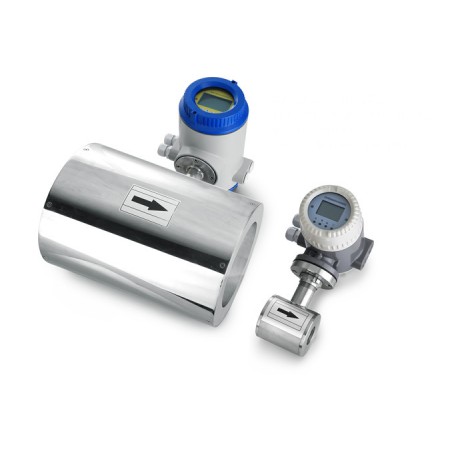


The RBEF Ceramic magnetic flow meters have ceramic liners in place of the typical elastomer liners commonly used in magnetic flow meters. Ceramic liners can tolerate higher temperatures and pressures than most other liner materials. Other liners can also release plasticisers and drying agents into the product in a process referred to as leaching.
The ceramic measuring tubes feature an outstanding combination of material properties including surface hardness and quality, mechanical stability and resistance to corrosion and temperature change. Benefits for the operator include ultimate accuracy and long-term stability as well as vacuum resistance and diffusion resistance. The versatile profile combined with the high accuracy, these flow meters are used in all sectors of industry.
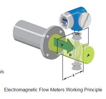
Faraday’s law of electromagnetic induction states that an inductive voltage is generated when a conductor moves through a magnetic field. This principle is used as the basis of flow measurement in the RBEF electromagnetic flow meter. In the electromagnetic flow meter, the flowing fluid corresponds to the moving conductor as described in Faraday’s law.
UE ∞ B * D * v
The induced voltage UE is directly proportional to magnetic field intensity (B), electrode spacing (D) and average fluid velocity (v). Since magnetic field intensity (B) and the electrode spacing (D) are constant values, induced voltage UE is therefore directly proportional to the average flow velocity (v).
Q = (∏ * D2) / 4 * v therefore UE ∞ Q
The equation for calculating volumetric flow rate (Q) shows that the induced voltage (UE) is linear and directly proportional to the average velocity (v). In the flowmeter transmitter, the induced voltage (UE) from the electrodes is used to calculate volumetric flow rate (Q) based upon the pipe’s internal diameter.
UE = Induced voltage
B = Magnetic field strength
D = Electrode spacing
V = Fluid velocity
Q = Instantaneous volumetric flow rate
RBEF Ceramic Electromagnetic Flow meter Features
RBEF Ceramic Electromagnetic Flow meter Specification:
No moving parts;
Fluid: for liquids
Mounting: Tri-clamp or Wafer
Material: Ceramic liner and Electrode,
Other characteristics: compact and remote type
Protection level: IP65 or IP67
Domain: Highly aggressive and abrasive fluids,
Process pressure: 9.8 bar (142.14 psi)
Process temperature: Min.: -40 °C (-40 °F); Max.: 180 °C (356 °F)
Flow velocity: Min.: 0.25 m/s (0.82 ft/s) Max.: 12 m/s (39.37 ft/s)
RBEF Ceramic Electromagnetic Flow meter Model Selection:
Tri-clamp Sanitary Electromagnetic Flow Meter Ordering Code
|
RBEF- |
DN |
- |
- |
- |
- |
- |
- |
- |
- |
- |
- |
- |
- |
- |
|
|
|
1 |
2 |
3 |
4 |
5 |
6 |
7 |
8 |
9 |
10 |
11 |
12 |
13 |
14 |
15 |
|
1 Nominal Diameter(mm)/ [inches](1)
|
||||||||||||||||||||||||||||||||
|
2 Flange Rating(1)
|
||||||||||||||||||||||||||||||||
|
3 Electrode Material
|
||||||||||||||||||||||||||||||||
|
4 Lining Material
|
||||||||||||||||||||||||||||||||
|
||||||||||||||||||||||||||||||||
|
7 Environmental Protection Class
|
||||||||||||||||||||||||||||||||
|
8 Explosion Proofing
|
||||||||||||||||||||||||||||||||
|
9 Configuration – sensor/transmitter
|
||||||||||||||||||||||||||||||||
|
10 Power Supply
|
||||||||||||||||||||||||||||||||
|
11 Display and Programming
|
||||||||||||||||||||||||||||||||
|
12 Output and Input
|
||||||||||||||||||||||||||||||||
|
13 Calibration Specification
|
||||||||||||||||||||||||||||||||
|
14 Flow Tube Configuration
|
||||||||||||||||||||||||||||||||
15 Special Function
|
0 |
No |
R |
IR Remote |
|
T |
Power off timer |
H |
Cumulative hours |
|
Q |
Quantitative control |
J |
Relay Output |
RBEF Ceramic Electromagnetic Flow meter Applications
In different industries:
Magmeters
Ultrassonic Flow Meter
Coriolis Mass Flow Meter
Other Flow Instrument