


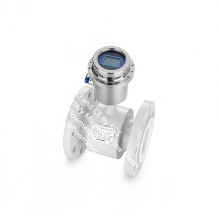


RBEFB battery operated Magnetic flow water meter is designed specifically for the water industry to meet the city's water supply to ensure the accurate calculation, the scene is widely used in places without power supply, such as urban water supply, sewage treatment, water conservancy and other industries.
Battery-powered electromagnetic flow meter specially designed sensor excitation system, and high-performance lithium battery-powered systems, and uses 16-bit AMD embedded processor power, with all-digital signal processing, measurement stability, high measurement accuracy, anti - Interference ability, and other features, automatic bi-directional flow measurement, on-site instantaneous flow of positive and negative cumulative total to show that self-diagnosis alarm FAULT Far GSM wireless data functions, the user through the powerful GSM / GPRS remote management software system can flow Far total wireless data storage functions.
The magnetic flow meter fulfils the special customer demands to water applications within abstraction, distribution network, revenue metering as well as irrigation.
RBEFB Battery operated Magnetic Flow Meter Features:
RBEFB Battery operated Magnetic Flow Meter Technical parameters
|
Diameter |
DN10-DN1200 DN150- DN3000 (Also optional plug-in battery-powered electromagnetic flow meter) |
|
Pressure |
0.6~4.0Mpa(Special pressure customizable) |
|
Accuracy |
±0.5%、±1.0% |
|
Measuring range |
0 ~±12m / s |
|
Media Measurement (conductivity) |
> 20μs/cm |
|
medium temperature |
-10 ℃ ~ 90 ℃, ≤180℃(Remote type) |
|
ambient temperature |
-40 ℃ ~ 65 ℃ |
|
power supply |
3.6V/DC built-in lithium battery-powered, continuous working hours, more than 6 years |
|
Electrode materials |
316L stainless steel, HC, HB, titanium, tantalum, platinum / iridium alloy |
|
lining materials |
poly chloroprene rubber, polyurethane rubber, PTFE, F46, PFA |
|
Connections |
flange type, plug-in, clip pattern |
|
Structure in the form of |
a body divided body |
|
Level of protection |
IP68 |
|
Display |
LCD large-screen liquid crystal display instantaneous flow of positive / reverse the cumulative total and prompt warning |
|
Output |
Local display(optional pressure display): 1. GPRS, RS485 can be powered by battery 2. 4-20mA, Pulse and 4-20mA+Hart is powered by 12-30VDC |
|
Means of communication |
GPRS(compact and remote type), GSM, Mobus, Hart |
Appearance and size of the installationTable
|
Diameter |
Pressure |
Dimension(mm) |
Weights |
Remark |
||||
|
(mm) |
MPa |
a |
b |
C |
d |
kgs |
|
|
|
25 |
4.0 |
200 |
146 |
121 |
115 |
5.5 |
||
|
32 |
200 |
161 |
139 |
140 |
6.5 |
|||
|
40 |
200 |
161 |
139 |
150 |
6.5 |
|||
|
50 |
200 |
199 |
160 |
165 |
7.5 |
|||
|
65 |
200 |
209 |
173 |
185 |
12 |
|||
|
80 |
200 |
216 |
173 |
200 |
12 |
|||
|
100 |
1.6 |
250 |
267 |
233 |
220 |
14 |
||
|
125 |
250 |
278 |
233 |
250 |
19 |
|||
|
150 |
300 |
308 |
257 |
285 |
22 |
|||
|
200 |
1.0/1.6 |
350 |
366 |
291 |
340 |
45 |
||
|
250 |
400 |
418 |
331 |
395 |
65 |
|||
|
300 |
500 |
481 |
381 |
445 |
95 |
|||
|
350 |
500 |
529 |
428 |
505 |
135 |
|||
|
400 |
600 |
587 |
483 |
565 |
170 |
|||
|
450 |
600 |
620 |
533 |
615 |
210 |
|||
|
500 |
600 |
675 |
585 |
670 |
230 |
|||
|
600 |
600 |
790 |
685 |
780 |
255 |
|||
|
700 |
700 |
900 |
800 |
895 |
315 |
|||
|
800 |
800 |
1015 |
905 |
1015 |
335 |
|||
|
900 |
900 |
1115 |
1002 |
1115 |
435 |
|||
|
1000 |
1000 |
1230 |
1110 |
1230 |
595 |
|||
|
1200 |
1200 |
1420 |
1295 |
1405 |
720 |
|||
Battery Working Time
Table 4.1.Corresponding Table of Battery life and Interval Measurement Time
(Excitation Mode 1)
|
Cycle Measuring Time |
50mA Excitation Use Time |
20mA Excitation Use Time |
|
30S |
120 months |
200 months |
|
15S |
60 months |
100 months |
|
14S |
56 months |
93 months |
|
13S |
52 months |
86 months |
|
12S |
48 months |
79 months |
|
11S |
44 months |
73 months |
|
10S |
40 months |
66 months |
|
9S |
36 months |
59 months |
|
8S |
32 months |
53 months |
|
7S |
28 months |
46 months |
|
6S |
24 months |
39 months |
|
5S |
20 months |
33 months |
|
4S |
16 months |
26 months |
|
3S |
12 months |
19 months |
Table 2 Battery Life Coefficient Corresponding Excitation Mode
|
Excitation Mode |
Mode 1 |
Mode 2 |
Mode 3 |
Mode 4 |
|
Battery Life Coefficient |
1.0 |
0.85 |
0.75 |
0.60 |
When the sensor has large diameter, the corresponding excitation cycle is long (see excitation mode parameter), therefore there is more power consumption.
RBEFB Battery operated Magnetic Flow Meter Model Selection
|
RBEFB- |
DN |
- |
|
- |
|
- |
|
- |
|
- |
|
- |
|
- |
|
- |
|
- |
|
- |
|
- |
|
- |
|
- |
|
|
|
1 |
|
2 |
|
3 |
|
4 |
|
5 |
|
6 |
|
7 |
|
8 |
|
9 |
|
10 |
|
11 |
|
12 |
|
13 |
|
14 |
|
1 Nominal Diameter(mm)/ [inches] (1)
|
|||||||||||||||||||||||||||||
|
2 Flange Rating (1)
|
|||||||||||||||||||||||||||||
|
3 Electrode Material
|
|||||||||||||||||||||||||||||
|
4 Lining Material
|
|||||||||||||||||||||||||||||
|
5 Grounding and Lining Protection
|
|||||||||||||||||||||||||||||
|
6 Max. Process Temperature
|
|||||||||||||||||||||||||||||
|
7 Environmental Protection Class
|
|||||||||||||||||||||||||||||
|
8 Explosion Proofing
|
|||||||||||||||||||||||||||||
|
9 Configuration – sensor/transmitter
|
|||||||||||||||||||||||||||||
|
10 Power Supply
|
|||||||||||||||||||||||||||||
|
11 Display and Programming
|
|||||||||||||||||||||||||||||
|
12 Output and Input
|
|||||||||||||||||||||||||||||
|
|
|||||||||||||||||||||||||||||
|
13 Calibration Specification
|
|||||||||||||||||||||||||||||
|
14 Flow Tube Configuration
|
(1) Line size selection will be inches for ANSI Class 150/300 rating selection, DIN size for all other ratings
(2) Order longer cable length separately
(3) Ceramic liner and electrodes is with wafer type only
RBEFB Battery operated Magnetic Flow Meter (Emag flow meter) Application
Water & Wastewater industry
Pulp Paper & Power Generation industry
Irrigation System
Leakage Detection
HVAC Building Automation System
Smart Metering
Chemical Industry & Refinery Petrochemical industry
Food and Beverage industry