


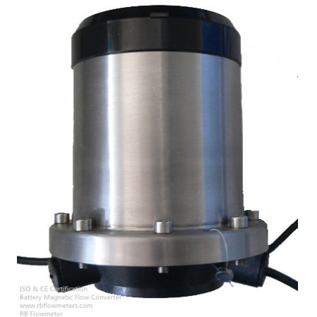


RBEFB Battery Powered Electromagnetic Flow Converter/Transmitter is a kind of battery powered electromagnetic converter. This electromagnetic converter is capable of being used together with common electromagnetic flow meter sensor, with the flow rate measurement accuracy up to 0.5 level. A new type of battery powered meter will be developed by connecting the RBEFC-B converter to a common electromagnetic flow meter.
The standard configuration of RBEFC-B battery powered electromagnetic converter has a lithium battery, which is capable of working 3 to 6 years consecutively. If a high-capacity battery is applied, the convertor will have longer working time.
RBEFC-B battery powered electromagnetic converter has GPRS and CDMA wireless data transmission function, RS485modbus protocol (external power supply or battery-powered) communication function, and SRD mode wireless network communication system to realize date collection and management.
Stainless steel outer covering and infrared remote control is applied to RBEFC-B battery powered electromagnetic converter to meet IP68-level seal protection requirement, which means the convertor can be used in underground and other damp places.
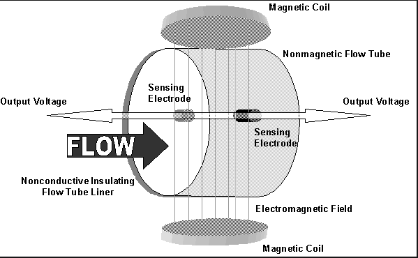
Faraday’s law of electromagnetic induction states that an inductive voltage is generated when a conductor moves through a magnetic field. This principle is used as the basis of flow measurement in the RBEF electromagnetic flow meter. In the electromagnetic flow meter, the flowing fluid corresponds to the moving conductor as described in Faraday’s law.
UE ∞ B * D * v
The induced voltage UE is directly proportional to magnetic field intensity (B), electrode spacing (D) and average fluid velocity (v). Since magnetic field intensity (B) and the electrode spacing (D) are constant values, induced voltage UE is therefore directly proportional to the average flow velocity (v).
Q = (∏ * D2) / 4 * v therefore UE ∞ Q
The equation for calculating volumetric flow rate (Q) shows that the induced voltage (UE) is linear and directly proportional to the average velocity (v). In the flowmeter transmitter, the induced voltage (UE) from the electrodes is used to calculate volumetric flow rate (Q) based upon the pipe’s internal diameter.
UE = Induced voltage
B = Magnetic field strength
D = Electrode spacing
V = Fluid velocity
Q = Instantaneous volumetric flow rate
Table 1 Corresponding Table of Battery life and Interval Measurement Time
(Excitation Mode 1)
|
Cycle Measuring Time |
50mA Excitation Use Time |
20mA Excitation Use Time |
|
30S |
120 months |
200 months |
|
15S |
60 months |
100 months |
|
14S |
56 months |
93 months |
|
13S |
52 months |
86 months |
|
12S |
48 months |
79 months |
|
11S |
44 months |
73 months |
|
10S |
40 months |
66 months |
|
9S |
36 months |
59 months |
|
8S |
32 months |
53 months |
|
7S |
28 months |
46 months |
|
6S |
24 months |
39 months |
|
5S |
20 months |
33 months |
|
4S |
16 months |
26 months |
|
3S |
12 months |
19 months |
Table .2 Battery Life Coefficient Corresponding Excitation Mode
|
Excitation Mode |
Mode 1 |
Mode 2 |
|
Battery Life Coefficient |
1.0 |
0.85 |
When the sensor has large diameter, the corresponding excitation cycle is long (see excitation mode parameter), therefore there is more power consumption.
For 20mA excitation, sensor excitation coil resistance: 70 to 110 Ω (two coils in series) (recommended)
For 35mA excitation, sensor excitation coil resistance: 50 to 70 Ω (two coils in series)
For 50mA excitation, sensor excitation coil resistance: 30 to 50 Ω (two coils in series)
Sensor flow signal strength: 50 to 100 mV (1m/s)
Note: Special note is necessary to order excitation coil resistance
Note: When doing the flow correction, if corrected sensor coefficient is around 1.0000, it is indicating that the flow sensor signal strength meets the requirements. If corrected sensor coefficient is greater than 1.0000, it is indicating that flow sensor is with low sensitivity. If corrected sensor coefficient is less than 1.0000, it is indicating that the flow sensor is with high sensitivity. If flow sensor with high sensitivity, stability and conducive of the flow meter measurement accuracy is better.
Generally, RBEFC-B converter can achieve good matching if ordinary sensor of 250mA excitation converter produced by our company is equipped and correction coefficient is less than 1.0000.
| RBEFB Battery Magentic Flow Converter Model Selection | |||||||||||
| RBEFB- | X | X | X | X | |||||||
| C5 | Compact(IP65) | ||||||||||
| R5 | Remote(IP65) | ||||||||||
| C8 | Compact(IP68) | ||||||||||
| R8 | Remote(IP68) | ||||||||||
| Output | |||||||||||
| N | No output | ||||||||||
| RB5 | RS485, 3.6V battery power supply, IP65 | ||||||||||
| RB8 | RS485, 3.6V battery power supply, IP68 | ||||||||||
| RP8 | RS485, 12-24V power supply,IP68 | ||||||||||
| GC8 | GPRS-Compact with 3.6V Battery powered,IP68 | ||||||||||
| GR8 | GPRS-Remote with 3.6V Battery powered, IP68 | ||||||||||
| GR5 | GPRS and RS485 two-way communication, 3.5V battery and DC12-24V two power supply, IP65 | ||||||||||
| GD5 | GPRS, 3.5V battery and DC12-24V two power supply, IP65 | ||||||||||
| A | 4-20mA with 12-24VDC or External battery,IP68 | ||||||||||
| P | Pulse with 12-24VDC or External battery, IP68 | ||||||||||
| AH | 4-20mA+Hart (IP68),12-24VDC or External battery, IP68 | ||||||||||
| Function selection | |||||||||||
| N | No | ||||||||||
| P | With pressure | ||||||||||
| Battery life | |||||||||||
| A | 3-6 years | ||||||||||
| B | More than 6 years | ||||||||||
Battery Magnetic Flow Converter /Transmitter Application:
We Supply:
Catalog- Electromagnetic Flow Converter/Transmitter (Battery Type)
Manual - Magnetic Flow Converter/Transmitter (Battery Type)
Other Files -Mag Converter/Transmitter (Battery Type)
Magnetic Flow Meter
Ultrasonic Flow Meters
Coriolis Mass Flow Meter