


As a professional supplier and manufacturer of Electromagnetic Flow Meter, RB flowmeter has been supplying quality Electromagnetic Flow Meter to customers all over the world for over 16 years.
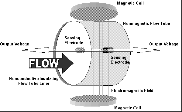
Faraday’s law of electromagnetic induction states that an inductive voltage is generated when a conductor moves through a magnetic field. This principle is used as the basis of flow measurement in the RBEF electromagnetic flow meter. In the electromagnetic flow meter, the flowing fluid corresponds to the moving conductor as described in Faraday’s law.
UE ∞ B * D * v
The induced voltage UE is directly proportional to magnetic field intensity (B), electrode spacing (D) and average fluid velocity (v). Since magnetic field intensity (B) and the electrode spacing (D) are constant values, induced voltage UE is therefore directly proportional to the average flow velocity (v).
Q = (∏ * D2) / 4 * v therefore UE ∞ Q
The equation for calculating volumetric flow rate (Q) shows that the induced voltage (UE) is linear and directly proportional to the average velocity (v). In the flowmeter transmitter, the induced voltage (UE) from the electrodes is used to calculate volumetric flow rate (Q) based upon the pipe’s internal diameter.
UE = Induced voltage
B = Magnetic field strength
D = Electrode spacing
V = Fluid velocity
Q = Instantaneous volumetric flow rate
|
Available Sizes |
ISO: DN15…DN3000 US: 1/2”…118” |
|
Accuracy |
Standard: ±0.5% (0.6m/sec to 15 m/sec) Optional: ±0.2% (1.0m/sec to 15 m/sec) |
|
Measurement Range |
Up to: 381,704 m3/hr 1,727,305 gal/min |
|
Maximum Flow Velocity |
12m/sec |
|
Measurement Resolution |
±1mm/sec |
|
Turndown |
Up to 1500:1 |
|
Process Connections |
GB Flange JIS Flange DIN Flange (DIN 2501) ANSI Flange (B16.5) Wafer Design |
|
Lining Materials |
Neoprene PTFE Polyurethane PFA Tefzel (PFA and Tefzel lining available with wire net reinforcement for negative pressure applications) Ceramic |
|
Electrode Materials |
316L Stainless Steel Hastelloy-C22 Hastelloy-B10 Titanium Tantalum Platinum/iridium Alloy Tungsten Carbide Coated 316L Stainless Steel Ceramic |
|
Removable Electrode |
In-situ Electrode Maintenance and Replacement Option Available |
|
Housing Protection Class |
IP65 IP67 (Compact versions only) IP68 (Remote Versions Only) |
|
Remote Transmitter |
Pipe Mount or Wall Mount |
|
Available Power Supplies |
85…265VAC 16…36VDC |
|
Transmitter Configuration Options |
Front Panel Keypad Hand Held Infrared Programmer |
|
Output Signals |
1 x Active Current Output 1 x Passive Current Output 1 x Frequency / Pulse Output |
|
Status Outputs |
2 x Contact / Status Outputs for Upper and Lower Flow Limit |
|
Digital Communication |
RS485 Modbus, GPRS |
|
Sizes |
Flanged (Metric) |
DN15…DN3000 |
||||||
|
Flanged (US) |
1/2”… 118” |
|||||||
|
Wafer Design |
DN15…DN100 |
|||||||
|
Nominal Pressure |
GB,JIS and DIN Flange |
0.6 MPa, 1.0 MPa, 1.6 MPa, 4.0 MPa |
||||||
|
ANSI Flange |
Class 150, Class 300 |
|||||||
|
Wafer Design |
1.6 MPa, 4.0 MPa |
|||||||
|
For additional pressure requirements, please contact manufacturer |
||||||||
|
Accuracy (pulse output) |
Standard |
±0.5% (0.6m/sec to 12 m/sec) |
||||||
|
Optional |
±0.2% (1.0m/sec to 12 m/sec) |
|||||||
|
Measurement Resolution |
±1mm/sec |
|||||||
|
Max Flow Tube Velocity |
SI: |
49 ft/s |
||||||
|
US: |
12 m/s |
|||||||
|
Ambient Temperature |
-25…+55°C / -13…+131°F |
|||||||
|
Relative Humidity |
5%…90% |
|||||||
|
Conductivity |
≥5 μS/cm |
|||||||
|
Transmitter Mounting Availability |
Compact type |
Sizes: DN15…DN1000 1/2”…40” |
||||||
|
Remote type |
Sizes: DN15…DN3000 1/2”… 118” |
|||||||
|
Note 1: Cable between flow tube and remote transmitter is type SMFE100 Note 2: Remote unit supplied with 10m cable as standard Note 3: Max cable length is 200m (650ft) |
||||||||
|
|
Material |
SI |
US |
|||||
|
Liner Material Options |
Neoprene (std) |
DN15…DN3000 |
1/2”…56” |
|||||
|
PTFE |
DN15…DN1000 |
1/2”…40” |
||||||
|
Polyurethane |
DN15…DN300 |
1/2”…12” |
||||||
|
PFA |
DN15…DN250 |
1/2”…10” |
||||||
|
PFA with optional wire reinforcement |
DN80…DN250 |
3”…10” |
||||||
|
Tefzel |
DN15…DN250 |
1/2”…10” |
||||||
|
Tefzel with optional wire reinforcement |
DN80…DN250 |
3”…10” |
||||||
|
|
ceramic liner and electrodes |
DN15…DN200 |
1/2”…8” |
|||||
|
Electrode Material Options |
316L stainless steel (std) |
DN15…DN3000 |
1/2”…56” |
|||||
|
Hastelloy – C22 |
DN15…DN1000 |
1/2”…40” |
||||||
|
Hastelloy – B10 |
DN15…DN1000 |
1/2”…40” |
||||||
|
Titanium |
DN15…DN250 |
1/2”…10” |
||||||
|
Tantalum |
DN15…DN250 |
1/2”…10” |
||||||
|
Platinum/iridium Alloy |
DN15…DN250 |
1/2”…10” |
||||||
|
316L with tungsten carbide coating |
DN15…DN600 |
1/2”…24” |
||||||
|
Grounding Options |
Flange Grounding |
DN15…DN3000 |
1/2”…56” |
|||||
|
Grounding Ring |
DN15…DN250 |
1/2”…10” |
||||||
|
Electrode Grounding |
DN50…DN3000 |
2”…56” |
||||||
|
Inlet protection ring |
DN50…DN300 |
2”…12” |
||||||
|
|
Type |
Liner |
Standard |
Optional |
||||
|
Max Process Temperature Limits |
Compact |
Neoprene |
80°C / 176°F |
120°C / 248°F |
||||
|
PTFE |
80°C / 176°F |
120°C / 248°F |
||||||
|
Polyurethane |
80°C / 176°F |
- |
||||||
|
PFA |
80°C / 176°F |
120°C / 248°F |
||||||
|
Tefzel |
80°C / 176°F |
- |
||||||
|
Remote |
Neoprene |
80°C / 176°F |
120°C / 248°F |
|||||
|
PTFE |
80°C / 176°F |
120°C / 248°F 180°C / 356°F |
||||||
|
Polyurethane |
80°C / 176°F |
- |
||||||
|
PFA |
80°C / 176°F |
120°C / 248°F |
||||||
|
Tefzel |
80°C / 176°F |
- |
||||||
|
Environmental Protection Class |
Compact |
IP 65 |
IP67 |
|||||
|
Remote |
IP 65 |
IP 68 |
||||||
|
Power Supply Options |
85…265VAC / 45…63Hz, 20VA |
|||||||
|
16…36VDC, 16VA |
||||||||
|
Display |
2 or 3 line backlit LCD |
|||||||
|
Configuration Access |
Front panel keypad |
|||||||
|
Hand held infrared remote control (optional) |
||||||||
|
Output Signals |
Active analog current output |
Max load resistance 0…1.5kΩ for 0…10mA 0…750Ω for 4…20mA |
||||||
|
Accuracy = same as pulse output ±0.1% of rate |
||||||||
|
Option: HART Protocol |
||||||||
|
Passive analog current output |
Requires 24Vdc external supply to operate |
|||||||
|
Accuracy = same as pulse output ±0.1% of rate |
||||||||
|
Pulse / frequency and alarm outputs |
Optically isolated open collector output powered either internally or externally Int. power: 28VDC with 1.2kΩ pull-up resistor Ext. power: ≤36VDC, max current 250mA |
|||||||
|
Digital Communications |
RS485 Modbus |
|||||||
|
GPRS (superimposed on current output) |
||||||||
|
All interfaces have built in lightning protection |
||||||||
|
Electrical isolation |
Isolation between all I/O and input power no less than 500V |
|||||||
|
Isolation between all I/O and ground no less than 500V |
||||||||
|
Isolation between flow tube and transmitter outputs no less than 500V |
||||||||
|
Standard |
JB/T 9248-1999 Electromagnetic Flow meter |
|||||||
Relation Flow Meter
产品图片 产品图片 产品图片 产品图片
Battery Magnetic Flow Meter Insertion Electromagnetic Flow Meter Magnetic Flow Converter Battery Magnetic Water Meter
|
RBEF- |
DN |
- |
|
- |
|
- |
|
- |
|
- |
|
- |
|
- |
|
- |
|
- |
|
- |
|
- |
|
- |
|
- |
|
|
|
|
1 |
|
2 |
|
3 |
|
4 |
|
5 |
|
6 |
|
7 |
|
8 |
|
9 |
|
10 |
|
11 |
|
12 |
|
13 |
|
14 |
15 |
|
1 Nominal Diameter(mm)/ [inches] (1)
|
||||||||||||||||||||||||||||||||||||
|
2 Flange Rating (1)
|
||||||||||||||||||||||||||||||||||||
|
3 Electrode Material
|
||||||||||||||||||||||||||||||||||||
|
4 Lining Material
|
||||||||||||||||||||||||||||||||||||
|
5 Grounding and Lining Protection
|
||||||||||||||||||||||||||||||||||||
|
6 Max. Process Temperature
|
||||||||||||||||||||||||||||||||||||
|
7 Environmental Protection Class
|
||||||||||||||||||||||||||||||||||||
|
8 Explosion Proofing
|
||||||||||||||||||||||||||||||||||||
|
9 Configuration – sensor/transmitter
|
||||||||||||||||||||||||||||||||||||
|
10 Power Supply
|
||||||||||||||||||||||||||||||||||||
|
11 Display and Programming
|
||||||||||||||||||||||||||||||||||||
|
12 Output and Input
|
||||||||||||||||||||||||||||||||||||
|
|
||||||||||||||||||||||||||||||||||||
|
13 Calibration Specification
|
||||||||||||||||||||||||||||||||||||
|
14 Flow Tube Configuration
|
15 Special Function
|
0 |
No |
R |
IR Remote |
|
T |
Power off timer |
H |
Cumulative hours |
|
Q |
Quantitative control |
J |
Relay Output |
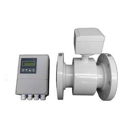
The RBEF electromagnetic flow meter (Emag. meters) range is designed to measure the volumetric flow of conductive liquids and slurries within closed pipelines in industries such as water & wastewater, chemical, petroleum, metal production, power, pharmaceutical, food & beverage, pulp & paper, etc.
The RBEF is the ideal instrument for measuring:
Note:
The minimum conductivity of the measured flow must be ≥ 5μS/cm for the meter to function correctly.
|
RBEF |
Flow meter Application Worksheet (Electromagnetic flow meter) |
|
|
Customer Name |
|
|
|
Contact |
|
|
|
Tel/Fax/Email |
|
|
|
Project Name |
|
|
|
Tag.No |
|
|
|
|
Process Parameters |
|
|
Pipe Spec / Material |
|
|
|
Process Connection |
|
|
|
Fluid Type |
|
|
|
Max Flow |
|
|
|
Nor. Flow |
|
|
|
Min. Flow |
|
|
|
Fluid Temperature |
|
|
|
Operating Pressure |
|
|
|
Measuring range |
|
|
|
Power Supply |
85 --- 265 VAC or 16 --- 36 VDC |
|
|
Accuracy % required |
( ±0.5 or ±0.2 ) |
|
|
|
Manufacturers Configuration Sheet |
|
|
Nominal Diameter mm |
|
|
|
Nominal pressure MPa |
|
|
|
Electrode Material |
|
|
|
Lining Material |
|
|
|
Grounding/ Protection |
|
|
|
Temperature Rating |
|
|
|
IP Protection Class |
|
|
|
EX Certification |
|
|
|
Configuration |
Compact or Remote |
|
|
Power Supply |
85 --- 265 VAC or 16 --- 36 VDC |
|
|
Programming Display |
|
|
|
Input/output signal |
|
|
|
Inspection |
|
|
|
Connection type |
|
|
|
Electric connection |
|
|
|
Special signal cable |
|
|
|
Mating Flange Set |
|
|
|
Accessory 1 |
|
|
|
Accessory 2 |
|
|
|
Model Number |
RBEF- |
|
|
Remark
|
|
|
Catalog
Manual
Other files
Magnetic_Flow_Meter
Ultrasonic Flow Meters
Coriolis Mass Flow Meter